Collider Tools 1.1 - UPDATE!

News / 13 September 2022

Hey folks,

There is a big update for collider tools :)! Collider Tools 1.1.


It contains a lot of new features improving the overall experience a lot.

  • Generate colliders per selected object or around the entire selection.
  • Create arbitrarily oriented minimum bounding boxes. You can generate automatically oriented box colliders with the lowest volume possible.
  • The entire physic materials system has been redone.
  • Collider groups are introduced and offer a more customizable way of grouping, selecting, organizing, and naming colliders according to their functionality. It replaces the old simple-complex system.
  • Regenerate naming. Change the collider naming after creation from UE to Unity.
  • Bug fixes and other new features.

Release Notes and documentation are already updated:

Quarry Bank Mill 3D #08 The mid-poly workflow

General / 12 July 2020

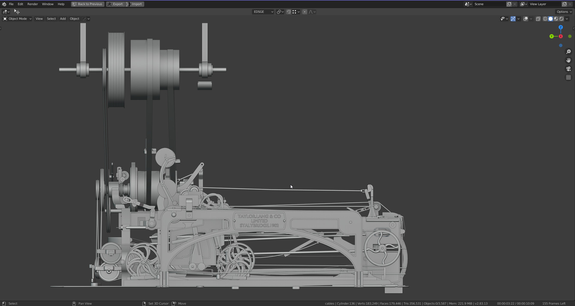
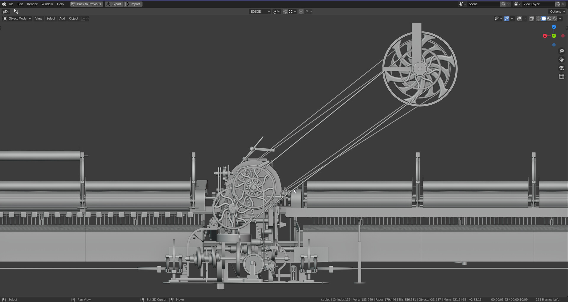
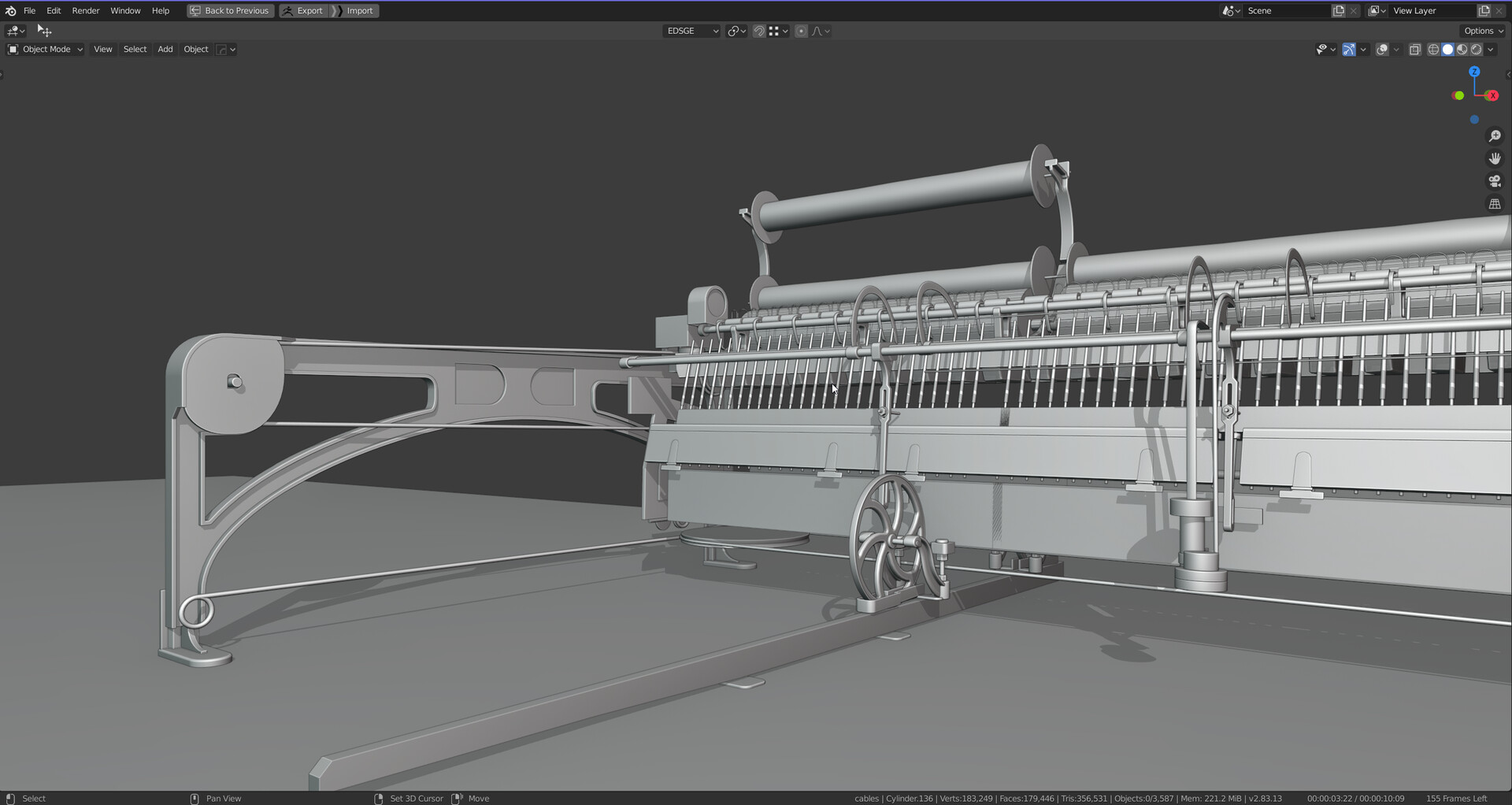
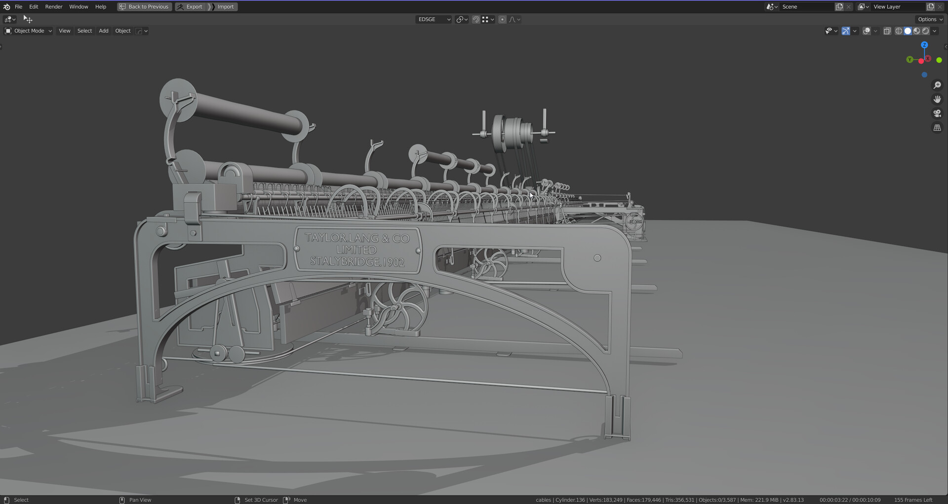
I want to share some useful techniques and tricks for the mid-poly workflow. First things first, what is it, why did I use it for my spinning mule and why should you care?

The Fundamentals

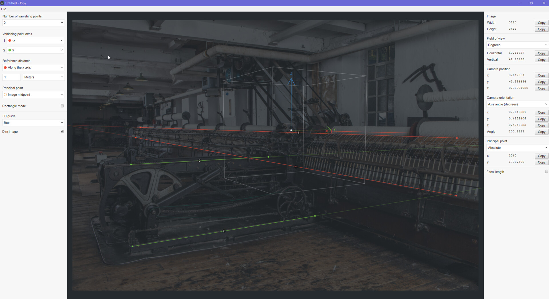
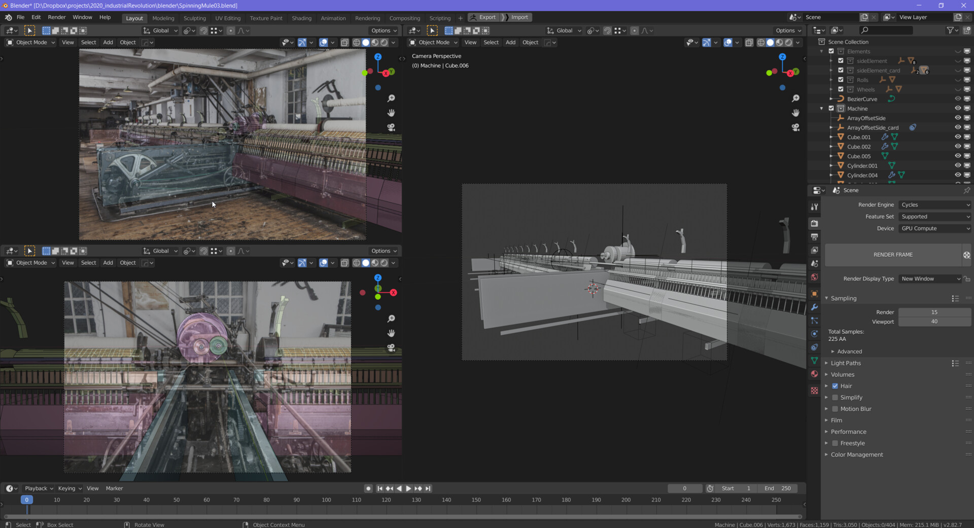
A mid-poly workflow is a popular approach for hard surface modeling in the video game industry. Huge AAA games like Star Citizen, Alien Isolation use it extensively in combination with other techniques like decals and trim sheets. I used this approach also in other projects I worked on, Black Mirror (2017), Letzte Worte, and VR-trainings from Innerspace. You can see all of them in my portfolio section. The workflow is heavily based on bevels, weighted normals, and the manipulation of vertex normal to influence the shading of a surface. It does not rely on additional support loops and is completely different from the subdivision modeling approach.

I won’t go into much detail here as there are a lot of resources available online. I can recommend the tutorials about hard surface modeling from Gleb Alexandrov. He has a dedicated video about Weighted normals and how to use them in Blender. He compares the results to other approaches and explains the workflow in-depth. Check it out.


The image beneath is from this video and illustrates the concept of weighted normals. The small arrows represent the vertex normals. By manipulating their direction, you can manipulate the shading of the object.

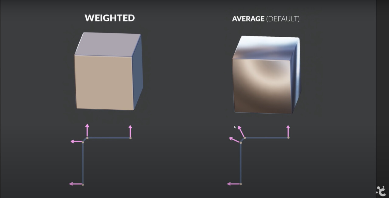
Source: Gleb Alexandrov (https://www.youtube.com/watch?v=sqGFhiP-2mc)

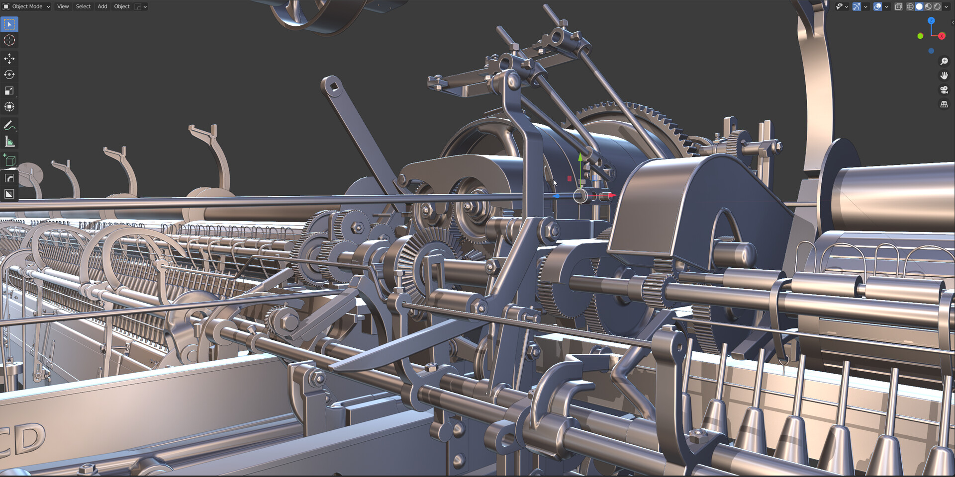
This approach is highly scalable and applicable to any asset complexity.

The Benefits: 

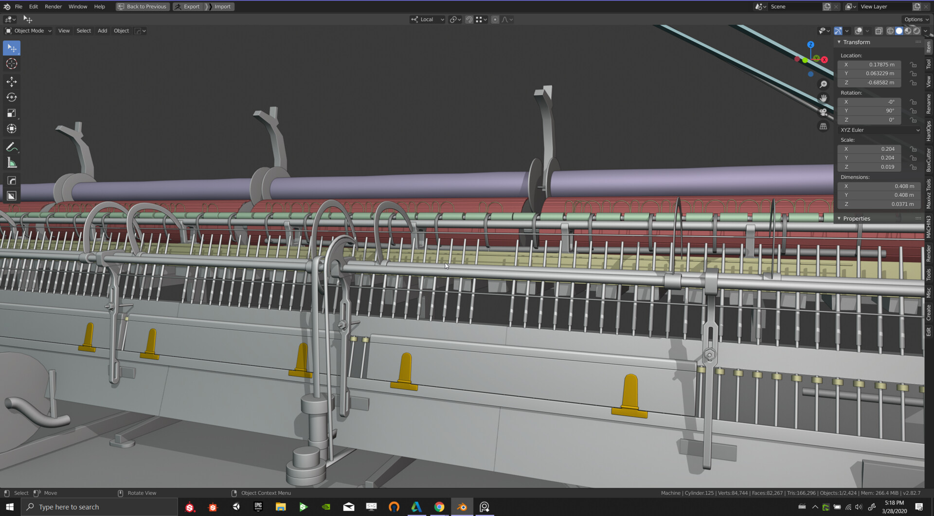
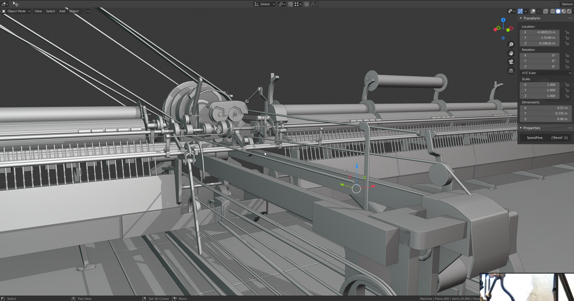
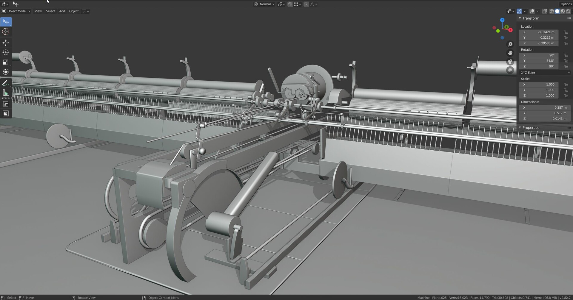
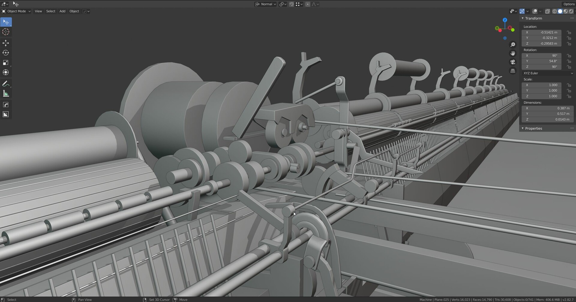
The workflow works best for hard surface assets like machines or modular environment pieces. In these cases, it provides a lot of benefits in flexibility, reusability, iterability, and performance. In contrast to the traditional high-poly and low-poly workflow you only create 1 version of the asset, the mid-poly. I find the baking process to be really limiting. Getting rid of this step removes a hugely destructive part of the pipeline. Once an asset is baked, every change becomes a lot of effort! Even small adjustments may require adjustments in both meshes, the UVs, rebaking of the texture maps, and adjustments in the final textures. While normal maps are essential to compensate for shading issues of the low poly in the conventional workflow, mid-polys use normal maps mainly to add micro detail. Baked normal maps would require huge texture resolutions for assets like the mule and are most of the time unique to the asset. The baking process would not be easy either. You need to separate the individual parts for baking to not bake normal information onto nearby components. Investing some more geometry to avoid normal baking seems like a good idea. Some additional benefits are:

  • No need for baking from another mesh
  • It is easier to use trim sheets and layered materials on these assets. The normal maps are just used to add micro detail but do not define bigger shapes. Both, trim-sheets and layered materials have inherent benefits in regard to flexibility and possible variations. You can replace the trim sheet or the base materials for the material layering to create different variations of the same asset without a heavy impact on the memory. Both approaches allow for easier reuse of the textures across different assets. I will go into more detail in future blog posts.
  • Mid-poly works much better for stereoscopic applications like VR. Conventional normal maps do not work properly for these applications and can just be used to add micro detail but not for bigger shapes.

Sounds great, should I always use this workflow? No. There are a lot of situations where you still want to use the conventional high-low poly workflow. A good example of that is smaller hero objects, where you want to have complete control over every single detail, assets with a lot of material variety, or objects with organic shapes.

 Additional Links


Quarry Bank Mill 3D #07 Modifiers and Wires

General / 16 May 2020

I want to share some modifier setups and the progress on the wires in this update with you. I already wanted to publish this blog last week but had some issues with getting the gifs to work.

Modeling

I try to keep the meshes as simple and non-destructive for as long as possible. This allows me to keep changing the shapes throughout most of the process with low effort. This way, I get a good impression of the final output while keeping the flexibility. I do not have to imagine how the mesh will look at the end, it's almost WYSIWYG. I can already preview the mesh from an early stage. Once I am happy with the result of the machine, I will apply the modifiers one by one. I will go through every single part and optimizing the shapes, topology after every applied modifier. Some examples for the modifier setups:

  1. Vertex Bevel to create the round shapes at the lower part of the object with a width percentage of 50%
  2. Decimate to remove the unnecessary geometry created by the vertex bevel. (set to planar with a angle limit of 2°)
  3. Solidify to give thickness to the geometry
  4. Bevel to create the rounded right corner using the bevel weight edge attribute, depending on the surrounding topology either activating or deactivating the Loop Slide attribute have a better result.
  5. Weld to merge the overlapping vertices introduced especially by the first bevel and its width percentage of 50%
  6. Bevel based on an angle of 35° to replace the sharp corners with bevels
  7. Triangulate with Minimum Vertices set to 5 to triangulate all n-gons.
  8. Weighted normal to improve the shading. This works the best if Face Influence is active and the prior bevels use the face straight mode affected and

Some more examples using similar techniques and modifier setups.

Here I use the complex mode in the solidify modifier in contrast to the first example. The complex mode can handle shapes like T profiles and offers additional settings.

I use additional Boolean modifiers for this example. The objects used to create the negative spaces are simple planes with vertex bevel (high bevel width and Clamp Overlap), weld and solidify modifiers. This way, the amount of edges on the holes can be adjusted by the be bevel segments in the cutter objects.

In this example I use hook modifiers to create controllers for changing the window the panel sizes and different array modifiers to repeat the base shape and later the entire window. I also use the Bevel profiles to create custom shapes of the wood edges.

Wires:

Creating the wires was the most challenging part of the machine so far. It is difficult for me to understand where the different ropes are attached to and what they drive. I tried out different approaches for creating them. Finally, I ended up using curves with hook modifiers. The hook is attached to an empty object. By moving, rotating, and scaling the hook empty I can manipulate the rope. Further, I can also parent the gears connected to the rope to the hook empty. Therefore, I can move the gears and deform the ropes automatically. The best thing about this is, rotating or scaling the hook empty will not affect the rope thickness. The bevel depth of the curve is independent from the scale and rotation of the hook empty. Just look at the last gif. It will explain it much better than this text :)

This setup will make it easy to rig the ropes as a nice side effect.

Quarry Bank Mill 3D #06

General / 19 April 2020

After spending the last blog post mainly focusing on technical tools, tricks and improvements, I will focus again on the progression I made on the mule itself. This update is a huge step forward in my option. Most of the areas have been defined and most of the mule is now at least partially in the 3D model.

After the unsuccessful hunt for references of the back side I decided to contact the Quarry Bank Mill directly and ask them for some reference images. The response was super nice, and they sent me immediately the few photos from below. Thank you so much! I doubt being able to recreate the backside in the same way as I do now without these images. And it is still a pain and forcing my skills to its limits.

Look at this insane rope system!  ! I totally underestimated these. It was so satisfying to finally solve one of them. 

Even after receiving the images from Quarry Bank I am missing information on some of the areas. These are hardly visible and therefore especially difficult to make. It will take me some more time to get them done. Currently I spent as much time looking through the references, technical drawings and similar machines to find hints for the missing pieces. All the parts are highly interconnected, and the machine can only work if every little screw is at its proper place. It is so rewarding that now more and more pieces fit together.

Quarry Bank Mill 3D #05

General / 10 April 2020

This update is mainly about workflow improvements and tools. I stumbled upon the “Dolly Zoom & Track Shift” on blender market. It makes it so much easier to imitate the focal length of the camera. The fspy tool already got me big way, but I noticed that the focal length was still slightly off. This tool finally alLowed me to adopt the FOV of the camera without moving the camera around and therefore improve the accuracy of the image plane. Unfortunately, this meant that the mule didn't match the image plane perfectly anymore and I had to slightly move a lot of parts around. I wish I knew this addon from the beginning. I will make the tool a fix part of my workflow when recreating objects from images. Here the link to the tool:
https://blendermarket.com/products/dolly-zoom--truck-shift

I also made some image planes for the sides that use a different aspect ratio. Unfortunately, the camera aspect ratio is always tied to the output resolution. It is therefore not possible to use a camera-based image plane in landscape and portrait mode at the same time. And when changing from one camera to another, you always need to change the resolution as well. I was thinking about writing an addon to organize my cameras but decided to focus on the actual modeling. Finally, I simply hard coded the different image sizes and assigned them to different buttons. I think it is a good compromise between not over engineering things and still being helpful. Further I created a custom Pie menu to toggle between them even faster:


As the scene is growing bigger and more complex I started to loose to overview on individual elements. At this point it gets important for me to structure and organize my scene better. I have therefore started to organize reusable parts in collections an arrange them in a library collection. Spliting the machine in individual components and organize them in the library collection is an ongoing process. 

The blender scene is currently organized in 3 main collections. I can use the number keys 1,2,3 to quickly toggle between them. 1) contains the components library, 2) contains the assembled scenes and 3) contains the image plane cameras and other utilities. Together with the possibility to overwrite collections in a individual viewport it allows me to see the assembled machine with the image plane while working on the instantiated elements in another view. 


Quarry Bank Mill 3D #04

General / 28 March 2020

Still a long way to go! I started color-coding different materials and parts to easier identify them. I should have done it much earlier. I have worked on different areas since the last time: I worked on the inner parts and back side of the central mechanical unit, I added more detail all over the machine and worked on important additions for the side modules.

Different parts of the machine are in different states now. Some areas are already fleshed out, while others are still missing essential components. Especially the central inner part is in an early stage. It is challenging due to the poor reference images I have. This is the main reference I have on this area:

Some more impressions of my progress. 


Quarry Bank Mill 3D #03

General / 23 March 2020

The progress is slowing down tremendously as the areas are either hard to see on the different pictures and videos or not seen at all. To find indication of the position of a certain gear etc. I must look through a lot of different resources. Especially about the back area I have only sparse information. I feel more like an engineer and detective, looking for clues, than an artist :D


Quarry Bank Mill 3D #02

General / 17 March 2020

A quick update. I fixed a lot of the bigger shapes. Adding smaller parts helps me a lot to understand the entire structure. I can see how the shapes are getting closer and closer to the reference images. A lot of areas that appeared symmetrical at the first but aren't actually. E.g., the number of modules on the left and right and the central cylindrical axis. Getting the shapes right is an evolution and takes time. But images tell more than words.

Did you know that you can change the visible collections per 3D view? This is super handy.


Quarry Bank Mill 3D #01

General / 14 March 2020

I have recently started to work on a cotton mill from the industrial revolution. The heart of the scene will be a realistic cotton self-acting spinning mule the 1800s. I got interested in the industrial revolution while playing Assassin’s Creed Syndicate. After reading a lot about the era I decided to go away from the portrayed iron industry and steam engines and focus on another essential part, the textile industry. Especially the aesthetics of the complex machines used inspired my decision. The main reference will be the Quarry Bank mill.


I have spent the whole last weekend to read articles and watch documentaries. I tried for hours to find out what machine it is, what's the purpose and the name. I gathered as much references as I could. I collected enough pictures and videos as well as sketches from historical books with similar machines. At some point I felt confident enough to start with the project. I have never been at the location myself and I won't be able to shoot reference pictures for myself! Therefore, finding good footage is essential. 

As a starting point I used fspy to create 2 Camera planes as reference and imported them in blender. 


This is the first, quick blocking. I started by freely model some of the shapes and then double check it with the camera planes. The shapes, proportions and positions aren't perfect, but a good starting point. It will be refined in the further process.